Where is the quality control of electronic scale molds reflected
The quality of electronic scale molds directly determines the accuracy, stability, and service life of core components such as the electronic scale shell, tray, and sensor mounting base. Its quality control needs to run through the entire process of "design processing trial mold mass production", focusing on five dimensions: dimensional accuracy, structural stability, material adaptability, surfac
The quality of electronic scale molds directly determines the accuracy, stability, and service life of core components such as the electronic scale shell, tray, and sensor mounting base. Its quality control needs to run through the entire process of "design processing trial mold mass production", focusing on five dimensions: dimensional accuracy, structural stability, material adaptability, surface quality, and durability. The specific control points are as follows:
1、 Dimensional accuracy control: the core of ensuring the "measurement correctness" of electronic scales
The core function of an electronic scale is "correct weighing", and the dimensional deviation of its mold components (such as tray support positions, sensor fixing slots, and housing assembly holes) will directly affect the weighing accuracy (usually requiring within ± 0.1mm), which needs to be controlled through the following methods:
1. Tolerance control of key dimensions
Strict tolerances are set for the "core dimensions that affect measurement": for example, the aperture tolerance of the sensor mounting hole needs to be controlled at H7 level (such as φ 12H7, tolerance range+0.018-0mm) to ensure a tight fit between the sensor and the mold components and avoid weighing data drift caused by gaps; The flatness of the tray support surface should be ≤ 0.05mm/m to prevent measurement errors caused by tray tilting.
During the processing, a "coordinate measuring instrument" is used for full-size inspection, with a sampling ratio of no less than 5% for each batch, and the focus is on verifying dimensional consistency (such as the size difference between cavities in multi cavity molds should be ≤ 0.02mm).
2. The precision of the fit between the mold cavity and the core
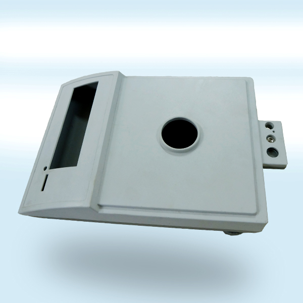
The shell of electronic scales is mostly a "top and bottom cover buckle structure", and the concentricity between the mold cavity (outer surface of the formed shell) and the core (inner surface of the formed shell) needs to be ensured to be ≤ 0.03mm, and the mold clearance should be ≤ 0.02mm:
During processing, the position of the mold cavity and core is ensured to correspond through "same reference positioning" (such as using the mold reference surface as a unified reference);
After the trial mold, check the gap at the buckle of the shell to avoid dust entering or loosening during assembly due to excessive gap, which may affect the stability of the internal circuit of the electronic scale.
2��、 Structural stability control: avoid mold deformation and component failure
Electronic scale molds (especially tray molds and large shell molds) need to withstand long-term injection pressure (usually 10-15 MPa) and temperature cycling (injection temperature 180-250 ℃). Structural stability control can prevent component scrapping caused by mold deformation. Specific points include:
1. Material and heat treatment control of mold steel
Choose high-strength mold steel: prioritize using S136 (corrosion-resistant, polished) or 718H (high hardness, deformation resistant) for the cavity and core, and use S50C (quenched and tempered to 28-32HRC) for the template to ensure overall rigidity of the mold;
Key components (such as cavity inserts) need to undergo "vacuum quenching+low-temperature tempering" treatment to achieve a hardness of 45-50HRC, while controlling the quenching deformation (deformation ≤ 0.01mm/100mm) to avoid cavity size deviation.
2. Uniformity of mold cooling system
Uneven mold temperature during injection molding can cause shrinkage and deformation of electronic scale components (such as the casing), and the cooling system must meet the following requirements:
The distance between the cooling water circuit and the surface of the mold cavity is uniform (usually 8-12mm), with a water circuit diameter of ≥ 8mm, ensuring that the temperature difference in each area of the mold cavity is ≤ 5 ℃;
For components with uneven wall thickness (such as sensor mounting bases, which may have a wall thickness of 3-8mm), a "conformal waterway" design is adopted to avoid shrinkage or deformation caused by local overheating.
3. Accuracy of guidance and positioning mechanisms
The guide column, guide sleeve, and positioning pin of the mold need to ensure high-precision fit to prevent cavity displacement during mold closing:
The clearance between the guide post and the guide sleeve is ≤ 0.005mm (using H6/g5 transition fit), and the clearance between the positioning pin and the pin hole is ≤ 0.003mm;
Before each batch of production, check the wear of the guide mechanism. If the wear of the guide column exceeds 0.02mm, replace it in a timely manner to avoid "wrong mold" and component scrap.
3��、 Material compatibility control: matching the functional requirements of electronic scale components
The electronic scale components need to be made of different materials according to the usage scenario (such as ABS/PP for the shell and PC/PA66 for the tray), and the mold needs to be adapted to the material characteristics to avoid quality problems caused by "material mold mismatch". Specific controls include:
1. Compatibility between cavity surface treatment and materials
For materials that are prone to sticking to molds (such as PVC, containing plasticizers and easy to stick cavities): the surface of the cavity needs to be treated with "chrome plating" (coating thickness 5-10 μ m, hardness ≥ 800HV) to improve surface smoothness (Ra ≤ 0.2 μ m) and prevent component strain during demolding;
For components that require weather resistance (such as ASA for outdoor electronic scale casings), the mold cavity needs to be polished and passivated to avoid surface impurities affecting the material's aging resistance.
2. Optimization design of gate and runner
The gate position and runner size need to match the fluidity of the material to avoid defects such as "material shortage" and "bubbles" in electronic scale components:
Materials with poor fluidity (such as PC): adopt a "large water mouth" design (gate diameter 3-5mm), with a channel cross-sectional area ≥ twice the gate cross-sectional area to ensure that the melt fully fills the mold cavity;
For "thin-walled components" (such as electronic scale panels with a wall thickness of 1.5-2mm): "hot runner+needle valve gate" is used to reduce gate marks and avoid insufficient filling caused by the cooling of the melt in the channel.
4����、 Surface quality control: meet the appearance and usage requirements of electronic scales
The shell, panel and other components of electronic scales require high surface quality (such as no scratches, shrinkage marks, bubbles), and the mold needs to control the surface quality through the following methods:
1. Polishing accuracy of cavity surface
The "visible surface" of the electronic scale shell (such as the front panel): The cavity needs to be polished to the "mirror level" (Ra ≤ 0.025 μ m, corresponding to polishing level A3) to avoid surface texture affecting the appearance;
Non visible surfaces (such as the inner side of the casing): Polish to Ra ≤ 0.8 μ m, balancing cost and assembly smoothness (reducing frictional resistance during component assembly).
2. Defect prevention and detection
Trial mold stage: Each mold samples and inspects the surface of the components, focusing on checking for "shrinkage marks" (uneven wall thickness), "bubbles" (fusion marks), and "flying edges" (mold clearance). When the defect rate exceeds 1%, the mold needs to be adjusted (such as expanding the gate and optimizing the cooling water circuit);
Mass production stage: Adopting a "visual inspection system" to automatically identify surface defects (detection accuracy of 0.1mm), replacing manual inspection, and avoiding missed detections (the missed detection rate of manual inspection is about 5%, and visual inspection can be reduced to less than 0.1%).
5、 Durability Control: Extend Mold Life and Mass Production Stability
Electronic scale molds usually require mass production of 100000 to 500000 molds. Durability control can reduce mold maintenance costs and ensure long-term production quality stability
1. Durability design of vulnerable parts
The vulnerable parts of the mold, such as the ejector pin, spring, and sprue sleeve, are made of "high-strength materials" (such as SKH51 high-speed steel for the ejector pin and SWOSC-V silicon chromium steel for the spring) and undergo "surface nitriding treatment" (nitride layer thickness of 5-8 μ m, hardness ≥ 900HV) to extend their service life (ejector pin life ≥ 100000 mold cycles, spring life ≥ 50000 mold cycles);
Design a "quick release structure" with a replacement time for vulnerable parts of ≤ 30 minutes, reducing downtime losses.
2. Mold maintenance and upkeep standards
Daily maintenance: After each production, clean the surface of the mold cavity with a specialized cleaning agent (such as a mold specific degreaser) to avoid residual slag corroding the mold; Check whether the cooling water circuit is blocked every week to ensure that the water circuit is unobstructed;
Regular maintenance: For every 10000 molds produced, the molds are "disassembled and inspected", including the wear of the mold cavity, clearance of the guide mechanism, and sealing of the cooling water circuit. At the same time, the mold cavity is "re polished" (when the surface roughness Ra exceeds 0.1 μ m) to restore surface accuracy.


 Home
Home
 Product
 Wechat
 Telephone